Downloads

Ma, C., Cheng, P., & Cai, C. Localization and Mapping Method Based on Multimodal Information Fusion and Deep Learning for Dynamic Object Removal. International Journal of Network Dynamics and Intelligence. 2024, 3(2), 100008. doi: https://doi.org/10.53941/ijndi.2024.100008

Article

Localization and Mapping Method Based on Multimodal Information Fusion and Deep Learning for Dynamic Object Removal

Chong Ma, Peng Cheng, and Chenxiao Cai *

School of Automation, Nanjing University of Science and Technology, Nanjing 210094, China

* Correspondence: ccx5281@njust.edu.cn


Received: 10 September 2023

Accepted: 25 December 2023

Published: 26 June 2024


Abstract: 
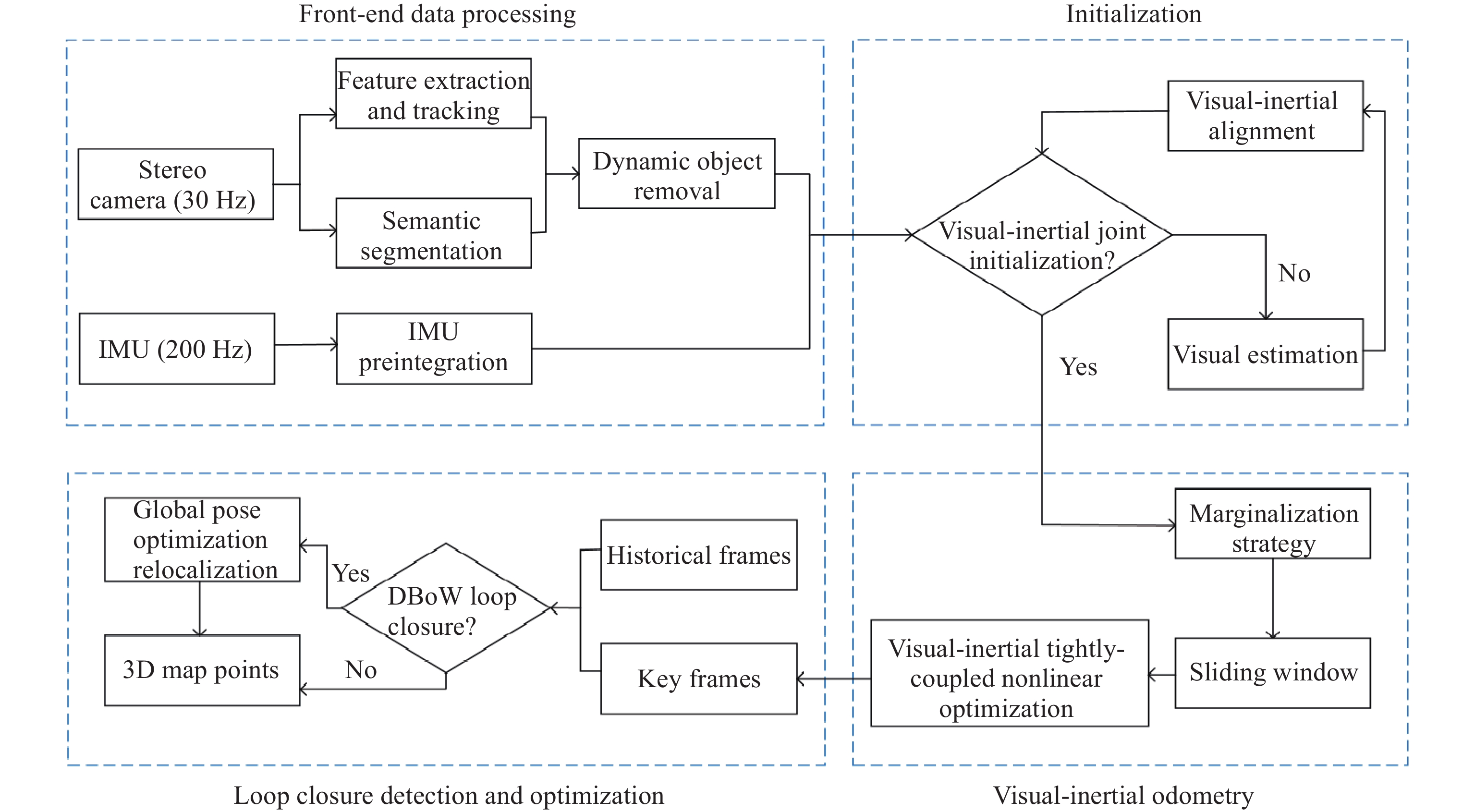
A simultaneous localization and mapping (SLAM) system is presented in this paper based on visual-inertial fusion to solve the pose estimation drift problem caused by weak texture environments or rapid robot movements. The camera and inertial measurement unit (IMU) is initialized through IMU pre-integration and visual front-end processing, and a tightly coupled residual function model is employed in the back-end to eliminate accumulated errors. To realize the real-time pose estimation in the complex loop scene, the sliding window optimization method based on the marginalization strategy is adopted to improve the optimization efficiency of the system, and the loop detection algorithm based on the bag-of-words model is exploited to solve the cumulative error problem generated during long-term operation. Furthermore, because of the interference (of complex scenes with dynamic targets) in system modeling and localization of the environment, this paper introduces a deep-learning semantic segmentation model to segment and eliminate dynamic targets. The system performance test is carried out based on the EuRoC dataset and the KITTI dataset. Finally, the experimental results illustrate that the proposed method has improved system robustness and localization accuracy compared with the pure vision algorithm and the visual-inertial fusion algorithm without removing dynamic targets.

Keywords:

visual-inertial system loop detection sliding window deep learning dynamic targets

1. Introduction

The simultaneous localization and mapping (SLAM) is a critical technology to achieve full automation of autonomous robots, and is widely employed in the unmanned driving, logistics distribution, environmental exploration, and other fields [1]. The SLAM refers to the process in which a mobile robot uses its multiple sensors to determine its pose and surrounding environment [2]. Davison A. J., et al. first proposed the monocular vision SLAM system framework (MonoSLAM) [3]. Note that the monocular vision system is constrained by external information in terms of spatial scale acquisition, and there is a large error in the depth information estimated from the geometric perspective. The BAD-SLAM proposed in [4] applied the RGB-D camera to determine the distance information between the target and itself. Note that the resulting performance is greatly affected by the light and the cost is high. Note that stereo cameras only need to calculate scale information by stereo matching binocular image information, which solves the problem of scale uncertainty of monocular cameras, but the cost is relatively low [5]. Therefore, stereo cameras are adopted to acquire image information in this paper, and the depth information is calculated by stereo matching.

Currently, stereo localization methods mainly include the optical flow methods and feature-based methods. The optical flow methods are based on the assumption of gray invariant [6], and are susceptible to interferences from the ambient light intensity. The feature-based methods are mainly divided into the point feature methods, edge feature methods, and block feature methods. Among them, the point feature methods show greater advantages in recognition and noise resistance than the other two methods [7]. Mei X., et al. [8] proposed a feature extraction method combining point features and line features to reduce the impact of weak texture environments on single-point features. Note that the introduction of line features makes subsequent feature matching difficult and time-consuming, and the real-time performance of the system drops significantly. Considering the repeatability and uniqueness of feature points, the SIFT algorithms [9], SURF algorithms [10], FAST algorithms [11], and ORB algorithms [12] have been proposed successively. Taking into account the illumination, scale, and rotation invariance of the image, the ORB algorithm is adopted in this paper. Additionally, the sole use of the camera sensor will lead to problems such as inaccurate depth information calculation and weak generalization ability under different lighting conditions. Therefore, the visual sensors and inertial measurement unit (IMU) are combined in this paper, and the high-frequency pose output characteristics of the IMU are used to ensure long-term tracking in complex environments and harsh conditions.

On the other hand, most existing open-source solutions assume that the working environment of the robot is static. Due to the existence of dynamic objects in real scenarios, the relative motion between the system and dynamic objects will lead to inaccurate localization information, redundancy and serious deviations in the construction of environmental maps [13]. So far, most object removal methods have solved the camera's motion model [14]. Note that existing SLAM system frameworks (presented under the assumption of a static environment) are disturbed when using feature or optical flow information to restore the motion posture in a dynamic environment. Even if the mismatched pairs are eliminated by the RANSAC algorithm, the estimation accuracy of motion information is still difficult to guarantee [15]. Accordingly, dynamic objects in the environment can be better eliminated by directly utilizing semantic information or multi-view geometric constraints to discriminate dynamic regions in an image.

Inspired by the above observations, this paper adopts the ORB feature extraction algorithm which has good robustness and real-time performance for complex scenes with weak textures, illumination, and large viewing angle changes. The main contributions of this paper are as follows.

1) Based on the ORB-SLAM algorithm framework [16], the IMU data is fused and combined with the visual front-end, and the sliding window optimization algorithm based on the marginalization strategy is introduced to build a tightly coupled model of the residual function to eliminate the cumulative errors.

2) Aiming at solving the problem of cumulative errors in the incremental map construction process under large-scale and complex loop-closing scenarios, the loop-closing detection and global optimization strategies are adopted based on the bag-of-words model, which effectively reduces the cumulative errors of the system in complex scenarios, and greatly improves the accuracy and robustness.

3) Since the static assumption principle is difficult to be satisfied in the actual scene of dynamic objects, the DeepLabV3 [17] semantic segmentation network is adopted. Furthermore, semantic information is used to identify and eliminate dynamic regions in images, which effectively improves the accuracy of system positioning and map construction.

2. Overall System Framework Design

The localization and mapping system proposed in this paper is shown in Figure 1. This system is based on multi-modal information fusion and deep learning dynamic target removal, and mainly includes a front-end data processing module, an initialization module, a visual-inertial odometer module, and a loop detection and optimization module.

Figure 1. Overall structure diagram of the system.

The front-end data processing module is mainly applied to front-end data processing of stereo cameras, including feature extraction, tracking, prior semantic segmentation, information processing and dynamic target removal. The oriented FAST and rotated BRIEF (ORB) feature extraction and fast approximate nearest neighbor search library (FLANN) methods [18] are used for feature extraction and tracking. The semantic segmentation dynamic target removal method adopts the DeepLabV3 semantic segmentation method based on the ResNET [19] backbone network, and uses the ADE20K pre-training model to perform dynamic target removal of semantic information on the KITTI public dataset. To prevent the redundant propagation of IMU state variables, the IMU preintegration method is used to improve the real-time performance of the system, and the image frame and the IMU frame are aligned for the case where the modal information measurement output frequencies are inconsistent.

The initialization module reserves a few frames in the sliding window, performs feature correspondence matching in the latest frame and historical frames, and carries out triangulation between any other frames after meeting the feature tracking number threshold and the disparity threshold. Furthermore, the perspective-n-pint (PnP) method proposed in [20] is employed to estimate the pose-motion information of the frame within the selected window.

In the visual-inertial odometry [21] module, since the back-end nonlinear high-dimensional optimization method cannot optimize the state variables at all moments, the constant change of the camera's perspective will make the earlier image frames lose the information of the current tracking landmarks. Therefore, this paper selects the most recent image frame and IMU frame as the optimization window [22] for pose estimation and optimization, discards the oldest frames in the window, and adds new keyframes to nonlinear optimization. Moreover, since there are still constraints in the frames (that need to be discarded) and other variables in the window, the Schur complement method is used to marginalize the historical frame state variables [23], and a visual-inertial tightly coupled residual function model is constructed. Finally, the graph optimization theory and the bundle adjustment (BA) algorithm are used to minimize the above residual function model to reduce the cumulative errors.

The loopback detection optimization module is used to realize the real-time operation of the system, but it cannot optimize all state variable information. As the system runs for a long time, the cumulative error of pose calculation still exists. To this end, the DBoW3 bag-of-words model is selected based on feature information for loop closure detection. By matching information between new keyframes and historical frames, we can determine whether there is a loop. Then, loop constraints are added between historical frames to update the residual optimization function model for global pose optimization.

3. Methods

3.1. Feature Extraction and Matching

The first step is the front-end data processing process. The stereo camera uses the ORB feature extraction and the FLANN fast nearest neighbor matching method. The specific process of front-end feature extraction and matching is shown in Figure 2, which includes the following steps.

1) Input grayscale image information.

2) Determine a circle with a radius of 3 pixels with any pixel point P as the center, as shown in Figure 2. Passing through 16 pixel points around the central pixel point P, the gray value I of the central pixel point P is calculated.

3) Set the threshold t. If there are 12 consecutive pixels among the 16 pixels that meet the threshold condition, then point P is recorded as a candidate feature point; otherwise, the pixel is filtered out. Continue to perform threshold screening of other pixel gray values.

4) Repeat steps 2 and 3 for each pixel.

5) To avoid the concentration of corner points, the non-maximum suppression method is used to calculate the score V of each candidate point, which can be determined by

(1)

where is the value of the pixel points on the circumference, is the set of pixel points whose brightness value is greater than , and is the set of pixel points whose gray value is smaller than . The adjacent candidate feature points with larger scores are retained as feature points, and the rest points are discarded.

6) Construct a Gaussian pyramid to achieve scale invariance of image features. The original image is scaled by the scale factor, and the pixel value of each layer of the image is calculated as

(2)

where k is the number of pyramid layers, and 1.2 is the scaling factor s. According to the scaling factor, an 8-layer image pyramid is constructed to obtain the images at different resolutions, so that the extracted feature points have scale invariance.

Figure 2. Flowchart of front-end feature extraction and tracking process.

Figure 3. Schematic diagram of FAST corner pixels.

7) To add the rotation invariance of the key points, the gray-scale centroid method is used to construct the direction vector, and the moment of the image block is defined as

(3)

Then, the centroid of the image block is determined through the moment of the image block as

(4)

Finally, connect the geometric center O of the image with the centroid C, and the feature direction can be obtained as

(5)

After extracting oFAST corner points, the rBRIEF descriptor of each feature point is calculated, and the approximate nearest neighbor matching algorithm (integrated into the FLANN open-source library) is used for feature matching. Finally, the random sample consensus (RANSAC) algorithm is used to eliminate mismatched pairs.

The comparative experiment results of the brute force matching method and the FLANN matching algorithm are shown in Figure 4 after ORB feature extraction. The images are selected from the machine hall 05 sequence provided by the public dataset EuRoC. From Figure 4, it can be seen that the performance of the feature extraction and matching method used in this paper is better than that of the traditional brute force matching method.

Figure 4. Illustration of image feature extraction and matching results. (a) Feature matching results using the brute-force matching method. (b) Matching results using the FLANN algorithm.

3.2. Dynamic Object Removal

Take into account the existence of dynamic targets in the actual environment. First, the relative motion between the dynamic target and the sensor will cause a relative deviation in translation and rotation based on the world coordinate system. Second, the identified and extracted landmark information on dynamic targets will lead to redundant map information, hence reducing the accuracy of map construction. To this end, the DeepLabV3 deep learning semantic segmentation method is used based on the ResNET backbone network, and the ADE20K pre-trained model is used to eliminate dynamic target information from the KITTI public data set.

The semantic segmentation method introduces multiple grids and improves the ASPP encoding structure which has two parts: the cascade model and ASPP model. Also, the Atrous spatial pyramid pooling (ASPP) model (suitable for multi-scale detection) is used in this work. The network architecture is shown in Figure 5. First, a deep residual network (ResNET) is used as a feature extractor to extract high-level semantic features from input images. Then, the ASPP model is applied, which consists of five parallel branches. Each branch includes a 1 × 1 convolutional layer and three 3 × 3 dilated convolutional layers with different dilation rates so as to increase the receptive field. Additionally, each dilation parameter is multiplied by the corresponding rate and multi-grid parameter. In the practical test, no additional block layer structures are added to the ASPP model, and the multi-grid parameter is set to be (1, 2, 4). Then, a global average pooling layer is used to obtain global information (followed by a 1 × 1 convolutional layer). The downsampling rate of the feature layer relative to the input image is set to be 8, and multi-scale parameters are set to be {0.5, 0.75, 1.0, 1.25, 1.5, 1.75} to obtain more scales. Then, the original width and height are restored through bilinear interpolation. Subsequently, the outputs of these five branches are concatenated along the channel dimension. Finally, a 3 × 3 convolutional layer and a 1 × 1 convolutional layer are used for bilinear interpolation and upsampling to restore the original image size.

Figure 5. The architecture of Deeplabv3 semantic segmentation based on the ResNET backbone network.

The original image and the segmentation image are shown in Figure 5, where the dataset selected in the figure comes from the public data set KITTI 01 sequence. The steps to remove segmented dynamic objects are as follows.

1) Set the RGB information and semantic information corresponding to the dynamic objects.

2) Use the semantic segmentation image as the mask image, and apply the image mask during the feature point extraction and matching processes.

3) Compare the pixel RGB values at the extracted feature points with the RGB values of the dynamic objects (using a threshold). Determine and remove the feature points corresponding to the dynamic objects.

4) Set the inflation boundary threshold to address the boundary issue of dynamic object regions where feature points may exist. If the number of feature points at the boundary exceeds 3, the boundary is inflated and the dynamic object points are deleted.

5) Feature tracking and matching may cause certain dynamic object points to be re-tracked. In this case, repeat Steps 2, 3, and 4 to perform secondary filtering of the dynamic object points.

3.3. IMU Preintegration

The relative pose measurement data of the IMU between two image frames can be obtained through IMU preintegration processing. First, based on the time scale of the continuous image frame , the image frame and the IMU measurement frame are frame-aligned, and IMU preintegration is performed between the aligned frames. Define the body coordinate system and the world coordinate system , and assume that the IMU coordinate system coincides with the body coordinate system. In the body coordinate system , the raw measurement value of the IMU accelerometer and the raw measurement value of the gyroscope are

(6)

where and represent the true values of the acceleration velocity and angular velocity of the IMU at time , respectively. and indicate the accelerometer bias and gyroscope bias of the IMU at time , respectively. means the transformation matrix from the world coordinate system to the body coordinate system at time . refers to the gravity acceleration in the world coordinate system , and and are generally regarded as zero. In the given alignment frame of the body coordinate system , the -th frame and the (+1)-th frame are recorded as and , respectively. In the world coordinate system , by integrating the IMU measurement values within the time interval , the position, speed, and rotation of the (+1)-th frame can be obtained as

(7)

where

(8)

with , , and representing the position, velocity, and rotation of the -th frame relative to the world coordinate system . stands for the timestamp between the -th frame and the (+1)-th frame. denotes the rotation matrix relative to the world coordinate system at time . To separate the preintegration optimization variables [24], the world coordinate system of formula (7) is transformed into the body coordinate system. Multiplying both sides of formula (7) by , we have

(9)

where

(10)

with , , and indicate the integrated values of the position, velocity, and quaternion (PVQ) between the -th frame and the (+1)-th frame in the body coordinate system . implies the rotation matrix relative to the -th frame in the body coordinate system at time .

The rotation matrix in the integration term is replaced by . In the initial frame , the rotation matrix in the body coordinate system is set to be , eliminating the dependence on the initial pose information through preintegration. Then, the discrete form of the preintegration using the midpoint method can be obtained as

(11)

3.4. Visual-Inertial Odometry

The visual-inertial odometry module uses the sliding window strategy to select the most recent image frames and IMU frame information as the optimization window for pose estimation and optimization. Considering that there is a coupling relationship between the historical frames (that need to be discarded) and the frames in the current window, the Schur complement method is used in this article to marginalize the historical frame constraint information. The prior information of the marginalized optimization variables is added to the back-end optimization residual in the function model.

Assume that the variable that needs to be retained is , and the variable that needs to be marginalized is . To solve the nonlinear least square problem in SLAM, we take the Gauss-Newton method as an example. The core is to solve which can be abbreviated as . Due to the sparsity of , the structure of can also be rewritten as . Therefore, the equation can be transformed into

(12)

where A is a block diagonal matrix with the dimension of each diagonal block being the same as the dimension of the camera parameter, and the number of diagonal blocks is equal to the number of camera variables.

Taking into account the diagonal block inversion characteristics, the Shure complement of formula (13) is performed to eliminate the non-diagonal part B of the upper right corner, which results in

(13)

Equation (13) can be rearranged as

(14)

After the elimination step, the incremental equation retaining the optimization variablecan be obtained as

(15)

Note that the constraint information of the variable is marginalized and retained, and only the variable is left. The marginal processing ensures that the constraint information of the historical state is preserved, the nonlinear optimization dimension is reduced, and the real-time performance of the system is improved.

The marginalization strategy with 3 visual poses and 5 landmark points is shown in Figure 6. The solid edges (between visual poses and landmark points) refer to the observation constraints, and the arrows (between adjacent visual poses) imply the IMU measurement constraints. After and are processed through the marginalization strategy, the constraints between and are increased (the connecting line is bold), and the constraint relationship between and is also increased.

Figure 6. Illustration of the marginalization strategy.

Next, define the full state vector of aligned intra-frame IMUs and the full state vector of feature points in the sliding window as

(16)

where represents the full state vector, and consists of the position , velocity , and rotation of the IMU in the world coordinate system of the -th aligned frame. and are the accelerometer bias and gyroscope bias of the IMU in the body coordinate system . indicates the displacement and rotation of the camera coordinate system relative to the body coordinate system , i.e., the camera extrinsic parameters. means the inverse depth information of the feature point, and is the time offset.

Based on the sliding window, the previous information of marginalization, IMU measurement residual and visual reprojection residual are fused. Three types of residuals are expressed as follows by using the dimension-independent Mahalanobis distance.

(17)

where stands for the marginalized prior information, represents the IMU measurement residuals between the -th frame and the (+1)-th frame, and denotes the visual measurement residual of the -th feature point first observed in the -th frame image. indicates the set of all IMU observations, and refers to the set of features observed at least twice in the current sliding window. implies the covariance matrix of the IMU preintegration noise, and means the covariance matrix of the visual observation noise. is the Huber norm defined as

(18)

The Huber norm is used as a robust kernel function to ensure that the error of each edge does not grow too large. Finally, using the graph optimization theory, the BA algorithm is used to minimize the residual function model mentioned above to reduce the accumulated errors resulting from long-term system operation.

3.5. Loop Closure Optimization

(19)

Perform the image frame similarity scoring via the cosine similarity or the norm. Taking the norm as an example, the image frame similarity scoring can be described as

(20)

Loop closure detection [25] is performed every time a new key frame arrives as an input. If no loop is detected, the visual words of the key frame are added, and the visual dictionary is updated and maintained. If a loop is detected, subsequent global pose optimization or relocation is performed.

In the subsequent loop closure optimization process , the pose graph optimization method is adopted to alleviate the computational pressure of incremental calculation. That is, the poses are only adjusted according to the constraints without considering landmark nodes.

Assume that there is a loop between the current frame and the historical frame . Since the pose information of the historical frame can be obtained through the pose graph or the output of the odometer, it is further assumed that the pose is a fixed constant, denoted as . Based on the original tightly coupled optimization residual function model, the residual function optimization model can be obtained as follows by incorporating the loop closure constraint information of the current frame and the historical frame.

(21)

where represents the feature set between the current frame and the historical frame . denotes the observation of the -th feature in the historical loop closure frame . The optimization terms in the model include the marginalization prior information, IMU measurement bias residuals, visual reprojection residuals, and loop closure constraint residuals. Since the pitch and roll angles of the IMU measurement data are quite considerable, only the four-degree-of-freedom pose graph is optimized for translation components and yaw components.

4. Experiments

In the system experiments, a desktop computer is applied to train the deep learning semantic segmentation model and verify the performance of the proposed system in this paper.

The computer is equipped with the Intel Core i7 8700k CPU @3.7GHz, 32GB DDR4 memory, GTX 1080Ti graphics card, Ubuntu 18.04 operating system, ROS Melodic version robot operating system, OpenCV3, Eigen, Pangolin, G2O[26], Ceres Solver, etc. Besides, programming is performed using C++ and Python languages.

The specific experimental verification employs the EuRoC dataset from the ETH Zurich and the KITTI data set, which are jointly produced by the Karlsruhe Institute of Technology in Germany and the Toyota American Institute of Technology. On this basis, the multi-modal information fusion localization and mapping experiments are carried out in the non-dynamic interference loop closure environment and the dynamic interference environment, respectively.

4.1. Experimental Setup in Static Loop Closure Environment Without Dynamic Interferences

The MH05 complex loop closure environment sequence dataset in the EuRoC dataset is selected for the multimodal information fusion localization and mapping experiment in the loopback environment without dynamic interferences. For data collection, the EuRoC data set is based on the AscTec firefly hexacopter micro-aircraft platform which does not contain dynamic objects, The localization accuracy can reach the sub-millimeter level. Specifically, the pose estimation performances are compared between the ORB-SLAM vision-only algorithm and the proposed VIO method. The ORB_SLAM algorithm is a purely visual algorithm released in 2015. Its front-end uses visual feature extraction and matching methods, and its back-end uses the BA optimization and loop detection methods based on the bag-of-words model.

The proposed method effectively fuses IMU inertial information based on the ORB-SLAM framework. The effectiveness is verified for the pure visual approach, the visual-inertial optimization method without loop closure, and the visual-inertial system with loop closure optimization. Figure 7 shows the pose estimation diagrams for relocalization with and without loop closure detection. In Figure 7, the green line denotes the output of the pose localization trajectory without loop closure optimization, the red line stands for the output of the localization pose trajectory with loop closure optimization, and the red connecting line means the occurrence of closures. Furthermore, the specific pose trajectory accuracy is represented by the absolute pose error between the estimated pose and the ground truth.

Figure 7. Comparison of pose estimation with and without loop closure detection and relocalization. (a) Trajectory plot without loop closure optimization. (b) Trajectory plot with loop closure optimization, where the red trajectory represents the optimized trajectory after loop closure.

Figure 8 and Figure 9 present the visual comparisons of the 3D pose trajectory with ground truth, and the 3D position and rotation attitude with ground truth. Figure 10 shows the comparison of absolute pose errors. In virtue of Figures 810, it is evident that the pose estimation accuracy of the proposed method is better than that of the pure visual localization method, and the performance is further improved with the introduction of loop closure optimization. To better explain and quantify the accuracy of the proposed system, various criteria are used for comparisons of absolute pose errors, including the root mean square error (RMSE), mean error, median error, standard deviation (std), minimum error, maximum error, and sum of squared errors (SSE). The specific error values are listed in Table 1.

Figure 8. Comparison of 3D pose trajectory with ground truth trajectory.

Figure 9. Comparison of 3D position and rotation attitude with ground truth.

Figure 10. Comparison of absolute pose errors.

Methods rmse mean median std min max sse
orb_salm 0.362 0.318 0.290 0.172 0.070 0.694 28.158
vio_noloop 0.194 0.180 0.156 0.072 0.074 0.390 41.721
vio_loop 0.154 0.146 0.139 0.050 0.024 0.269 17.360
Table 1 Absolute pose errors in localization and mapping experiment without dynamic interferences

It can be observed that in complex loop closure scenarios with significant variations of lighting conditions and localization loss risks of unmanned devices, the proposed system method without loop closure optimization improves the absolute pose estimation accuracy by 57.5% compared to the ORB-SLAM visual-only algorithm. With the introduction of loop closure optimization, the pose trajectory estimation accuracy further improves by 20.6% compared to the non-loop closure optimized approach. Overall, these results demonstrate 78.1% accuracy improvement of the proposed method compared to the pure visual localization methods. The front-end of this method can process image and IMU frames at a maximum speed of 43 frames per second, which is faster than the back-end optimization rate (15Hz), thereby meeting the real-time requirements of the system.

4.2. Experimental Setup in Dynamic Interference Environment

For the experiment in a dynamic interference environment, the KITTI dataset sequence 01 is selected. The KITTI dataset consists of two color cameras, two grayscale cameras, one GPS/IMU navigation device, and one 3D laser scanner. The data is collected from various real-world scenarios such as urban, rural, and highway environments, with the data synchronization and distortion removal process performed at a rate of 10Hz. The dataset also includes a significant amount of dynamic interfering objects. As such, the dynamic object segmentation is performed through the deeplabvV3 semantic segmentation network, and the dynamic object features are assessed and eliminated during the front-end feature extraction and tracking process. The comparison of feature points is shown in Figure 11 before and after dynamic object feature removal. We specifically compare the pose estimation output of our proposed method with that of the popular visual-inertial localization and mapping algorithm (VINS-Mono[27]). The VINS-Mono algorithm was published in 2018. Its front-end involves feature extraction and optical flow tracking along with the fusion of IMU information. Also, the back-end incorporates pose graph optimization and visual feature loop detection. The specific comparison result is presented in Table 2 in terms of absolute pose errors.

Figure 11. Comparison of dynamic objects before and after removal.

Methods rmse mean median std min max sse
vins_mono 6.615 6.164 5.838 2.402 2.234 19.795 41529.4
vio_dte 5.069 4.701 4.833 1.898 0.250 9.436 24645.2
Table 2 Absolute pose errors in localization and mapping under dynamic interference environments

Figure 12, Figure 13, and Figure 14 present visual comparisons of the 3D pose trajectory with ground truth, the 3D position and rotation attitude with ground truth, and the comparison of absolute pose error, respectively.

Figure 12. Comparison of the 3D pose trajectory with the ground truth trajectory.

Figure 13. Comparison of 3D position and rotation attitude with ground truth.

Figure 14. Comparison of absolute pose error.

By effectively removing dynamic object features through a deep learning-based semantic segmentation network, the effect of dynamic objects on pose estimation and mapping is significantly reduced. The pose estimation trajectory demonstrates 23.4% accuracy improvement of the proposed method compared to the VINS-Mono visual-inertial localization and mapping algorithm. The front-end data processing speed is 21Hz, which is faster than the back-end optimized output rate (15Hz), meeting the real-time requirements of the system.

5. Conclusions

This work has proposed a localization and mapping scheme for visual-inertial multi-modal information fusion and deep learning dynamic object removal. Through experiment verification and testing, the following conclusions can be drawn.

1) This study has cleverly solved the problem of traditional pure visual optical flow tracking methods affected by factors such as environmental light intensity, and has improved the robustness and positioning accuracy of the system.

2) The constructed system has effectively overcome the problem of reduced sensor pose estimation accuracy caused by dynamic targets and information redundancy in scene map construction.

3) The visual-inertial constraint loop detection optimization method has successfully reduced the cumulative error caused by the continuous pose calculation of the system in long-running and complex loop scenes, thereby enhancing the adaptability of the system in various environments.

Future research directions include investigating and designing systems that incorporate laser depth information, as well as refining the subsequent mapping process. This would enable more accurate depth information for front-end pose estimation, as well as densification and refinement of scene reconstruction.

Author Contributions: Chong Ma: writing—original draft preparation, investigation; Peng Cheng: writing—review and editing; Chenxiao Cai: conceptualization, methodology, funding acquisition.

Funding: This work was supported by the National Natural Science Foundation of China (61973164, 62373192).

Conflicts of Interest: The authors declare no conflict of interest.

References

  1. Macario Barros, A.; Michel, M.; Moline, Y.; et al. A comprehensive survey of visual SLAM algorithms. Robotics, 2022, 11: 24. doi: 10.3390/robotics11010024
  2. Zheng, S.R.; Wang, J.L.; Rizos, C.; et al. Simultaneous Localization and Mapping (SLAM) for autonomous driving: Concept and analysis. Remote Sens., 2023, 15: 1156. doi: 10.3390/rs15041156
  3. Davison, A.J.; Reid, I.D.; Molton, N.D.; et al. MonoSLAM: Real-time single camera SLAM. IEEE Trans. Pattern Anal. Mach. Intell., 2007, 29: 1052−1067. doi: 10.1109/TPAMI.2007.1049
  4. Schöps, T.; Sattler, T.; Pollefeys, M. BAD SLAM: Bundle adjusted direct RGB-D SLAM. In Proceedings of the IEEE/CVF Conference on Computer Vision and Pattern Recognition, Long Beach, CA, USA, 15–20 June 2019; IEEE: New York, 2019; pp. 134–144. doi:10.1109/CVPR.2019.00022
  5. Shu, F.W.; Wang, J.X.; Pagani, A.; et al. Structure PLP-SLAM: Efficient sparse mapping and localization using point, line and plane for monocular, RGB-D and stereo cameras. In Proceedings of the 2023 IEEE International Conference on Robotics and Automation (ICRA), London, UK, 29 May–2 June 2023; IEEE: New York, 2023; pp. 2105–2112. doi:10.1109/ICRA48891.2023.10160452
  6. Guo, R.F.; Jia, R. Research on multi-information fusion target tracking algorithm based on LK optical flow method. Mod. Electron. Tech., 2019, 42: 55−59. doi: 10.16652/j.issn.1004-373x.2019.18.013
  7. Guan, Y.F. Research on Positioning Technology Combining Binocular Vision and Inertial Measurement Unit. Master’s Thesis, Harbin Institute of Technology, Harbin, China, 2020. doi:10.27061/d.cnki.ghgdu.2020.003647 (In Chinese)
  8. Mei, X.; Sun, X.; Zhou, M.C.; et al. On building an accurate stereo matching system on graphics hardware. In Proceedings of the 2011 IEEE International Conference on Computer Vision Workshops (ICCV Workshops), Barcelona, Spain, 6–13 November 2011; IEEE: New York, 2011; pp. 467–474. doi:10.1109/ICCVW.2011.6130280
  9. Lowe, D.G. Distinctive image features from scale-invariant keypoints. Int. J. Comput. Vision, 2004, 60: 91−110. doi: 10.1023/B:VISI.0000029664.99615.94
  10. Bay, H.; Tuytelaars, T.; Van Gool, L. SURF: Speeded up robust features. In Proceedings of the 9th European Conference on Computer Vision, Graz, Austria, 7–13 May 2006; Springer: Berlin/Heidelberg, Germany, 2006; pp. 404–417. doi:10.1007/11744023_32
  11. Rosten, E.; Drummond, T. Machine learning for high-speed corner detection. In Proceedings of the 9th European Conference on Computer Vision, Graz, Austria, 7–13 May 2006; Springer: Berlin/Heidelberg, Germany, 2006; pp. 430–443. doi:10.1007/11744023_34
  12. Rublee, E.; Rabaud, V.; Konolige, K.; et al. ORB: An efficient alternative to SIFT or SURF. In Proceedings of the 2011 International Conference on Computer Vision, Barcelona, Spain, 6–13 November 2011; IEEE: New York, 2011; pp. 2564–2571. doi:10.1109/ICCV.2011.6126544
  13. Saputra, M.R.U.; Markham, A.; Trigoni, N. Visual SLAM and structure from motion in dynamic environments: A survey. ACM Comput. Surv., 2019, 51: 37. doi: 10.1145/3177853
  14. Beghdadi, A.; Mallem, M. A comprehensive overview of dynamic visual SLAM and deep learning: Concepts, methods and challenges. Mach. Vision Appl., 2022, 33: 54. doi: 10.1007/s00138-022-01306-w
  15. Fischler, M.A.; Bolles, R.C. Random sample consensus: A paradigm for model fitting with applications to image analysis and automated cartography. Commun. ACM, 1981, 24: 381−395. doi: 10.1145/358669.358692
  16. Mur-Artal, R.; Montiel, J.M.M.; Tardos, J.D. ORB-SLAM: A versatile and accurate monocular SLAM system. IEEE Trans. Rob., 2015, 31: 1147−1163. doi: 10.1109/TRO.2015.2463671
  17. Chen, L.C.; Papandreou, G.; Schroff, F.; et al. Rethinking atrous convolution for semantic image segmentation. arXiv: 1706.05587, 2017.
  18. Hajebi, K.; Abbasi-Yadkori, Y.; Shahbazi, H.; et al. Fast approximate nearest-neighbor search with k-nearest neighbor graph. In Proceedings of the Twenty-Second International Joint Conference on Artificial Intelligence, Barcelona, Spain, 16 July 2011; AAAI Press: Palo Alto, 2011; pp. 1312–1317. doi:10.5555/2283516.2283615
  19. Szegedy, C.; Ioffe, S.; Vanhoucke, V.; et al. Inception-v4, Inception-ResNET and the impact of residual connections on learning. In Proceedings of the Thirty-First AAAI Conference on Artificial Intelligence, San Francisco, USA, 4 February 2017; AAAI Press: Palo Alto, 2017; pp. 4278–4284. doi:10.5555/3298023.3298188
  20. Gao, X.S.; Hou, X.R.; Tang, J.L.; et al. Complete solution classification for the perspective-three-point problem. IEEE Trans. Pattern Anal. Mach. Intell., 2003, 25: 930−943. doi: 10.1109/TPAMI.2003.1217599
  21. Servières, M.; Renaudin, V.; Dupuis, A.; et al. Visual and visual-inertial SLAM: State of the art, classification, and experimental benchmarking. J. Sens., 2021, 2021: 2054828. doi: 10.1155/2021/2054828
  22. Engel, J.; Koltun, V.; Cremers, D. Direct sparse odometry. IEEE Trans. Pattern Anal. Mach. Intell., 2018, 40: 611−625. doi: 10.1109/TPAMI.2017.2658577
  23. Lin, Z.L.; Zhang, G.L.; Yao, E.L.; et al. Stereo visual odometry based on motion object detection in the dynamic scene. Acta Opt. Sin., 2017, 37: 1115001. doi: 10.3788/AOS201737.1115001
  24. Qin, T.; Shen, S.J. Online temporal calibration for monocular visual-inertial systems. In Proceedings of the 2018 IEEE/RSJ International Conference on Intelligent Robots and Systems (IROS), Madrid, Spain, 1–5 October 2018; IEEE: New York, 2018; pp. 3662–3669. doi:10.1109/IROS.2018.8593603
  25. Mur-Artal, R.; Tardós, J.D. ORB-SLAM2: An open-source SLAM system for monocular, stereo, and RGB-D cameras. IEEE Trans. Rob., 2017, 33: 1255−1262. doi: 10.1109/TRO.2017.2705103
  26. Kümmerle, R.; Grisetti, G.; Strasdat, H.; et al. g2o: A general framework for graph optimization. In Proceedings of the 2011 IEEE International Conference on Robotics and Automation, Shanghai, China, 9–13 May 2011; IEEE: New York, 2011; pp. 3607–3613. doi:10.1109/ICRA.2011.5979949
  27. Qin, T.; Li, P.L.; Shen, S. J. VINS-Mono: A robust and versatile monocular visual-inertial state estimator. IEEE Trans. Rob., 2018, 34: 1004−1020. doi: 10.1109/TRO.2018.2853729